
Meeting SAE/USCAR-45 Standards: Optimizing Pull Force, Cpk, and Missing Strand Detection in Ultrasonic Wire Splicing
Publish Data:2026.5.22 Author: Hyusonic
For Tier-1 automotive wiring harness manufacturers, passing compliance audits is not merely about mechanical joint survival; it is about guaranteeing electrical stability over a vehicle’s lifetime. As automotive architectures transition from domain-controller systems to zonal E/E (Electrical/Electronic) layouts, high-voltage (HV) platforms demand connections that can withstand extreme thermal, environmental, and mechanical stresses.
Among these standards, SAE/USCAR-45 (Performance Specification for Welded Wire-to-Wire Splices) dictates the testing protocols for ultrasonically welded wire knots . Unlike traditional crimping or resistance welding, ultrasonic wire splicing has emerged as the definitive process to achieve zero-resistance solid-state joints. However, achieving consistent compliance in mass production requires a deep metallurgical understanding of process parameters, quality prediction control, and real-time defect isolation.
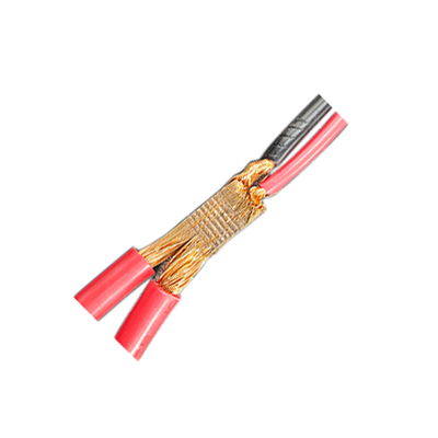
1. The Metallurgical Mechanics of Solid-State Diffusion in Copper Splicing
To understand why traditional soldering and crimping often fail modern automotive environmental testing, we must look at the weld interface. Soldering introduces a tertiary alloy with a different electrochemical potential, exposing the splice to galvanic corrosion under humid conditions. Crimping, on the other hand, relies purely on mechanical friction, which often leaves micro-gaps within the stranded wire bundles. Over time, road vibration causes these micro-gaps to expand, resulting in contact resistance spikes.
Ultrasonic metal welding (UMW) is a purely mechanical, solid-state joining process. Utilizing high-frequency lateral oscillations (typically at 20 kHz) under perpendicular pneumatic clamping pressure, the welding horn (sonotrode) grips the upper stranded copper wires. This transverse oscillation generates intense localized frictional scrubbing.
The primary mechanism involves:
Oxide Dispersion: The micro-scrubbing action fractures and disperses the natural cuprous oxide ($Cu_2O$) films and organic wire-drawing lubricants present on the bare copper strands.
Plastic Deformation: Under static pressure, the clean, non-ferrous copper atoms undergo localized plastic deformation, bringing their crystalline lattices into intimate contact.
Atomic Diffusion: Dynamic recrystallization occurs across the strand interfaces, forming a continuous grain structure without macroscopic melting.
Because the localized temperature remains well below the melting point of copper (typically 30% to 50% of the melting temperature $T_m$) , there is no thermal degradation of the surrounding PVC or cross-linked polyethylene (XLPE) insulation sleeves, nor is there any grain coarsening or embrittlement of the copper alloy.
2. Breaking Down USCAR-45 Test Protocols and Pull-Force Requirements
Compliance with SAE/USCAR-45 requires the welded wire splice to undergo a sequence of environmental exposures designed to simulate a road vehicle’s lifetime operational conditions :
Thermal Shock Exposure: Spliced samples are subjected to rapid temperature transitions from -40 °C to +150 °C for up to 1,000 continuous cycles, testing the joint against differential thermal expansion.
Temperature and Humidity Cycling: Samples are exposed to cyclic humid heat to evaluate resistance against atmospheric oxidation and moisture ingress.
Mechanical Abuse / Vibration Testing: Subjecting the splice to multi-axis harmonic vibrations to ensure the molecular bond resists fatigue cracking.
Pull Force & Mechanical Performance Criteria
Post-conditioning, the mechanical integrity of the splice is validated using a destructive tensile shear test. Most automotive specifications mandate that the splice must maintain a mechanical pull-off force exceeding 85% of the raw conductor’s ultimate tensile strength.
For example, when splicing standard multi-strand copper conductors, the pull rate must be maintained at a constant velocity of 25 mm/min . If a quality control team is validating a 20 AWG (0.5 mm² to 0.8 mm²) splice, the minimum acceptable tensile force before structural failure must exceed approximately 111 N (25 lbf) .
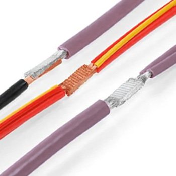
3. High-Confidence Quality Control: Achieving Process Capability (Cpk) and Under 3% Missing Strand Detection
In high-volume automotive manufacturing, relying on end-of-line destructive pull testing is insufficient. Process capability must be monitored in real-time, targeting process capability index values $C_{pk} \ge 1.33$ or $C_{pk} \ge 1.67$ to satisfy Six Sigma quality audits.
The Limits of Conventional Pneumatic Splicing
Standard pneumatic-cylinder ultrasonic welders can occasionally exhibit minor inconsistencies due to shop air-line pressure fluctuations. For instance, a traditional pneumatic welder typically can only detect missing strands if they exceed 5% of the total splice cross-sectional area (CSA). If an operator loads a 14 mm² wire knot with six missing strands out of 200, a pneumatic cylinder may fail to register the subtle height difference.
Micron-Level Microprocessor Validation
To achieve industry-leading missing strand detection below 3% of the total CSA, advanced splicing systems implement closed-loop process validation. This monitoring loop relies on high-resolution linear encoders (measuring compaction height in microns) and real-time generator feedback :
Pre-Weld Height Verification: Before the 20 kHz acoustic vibration is triggered, the system applies a pre-clamping force and measures the initial compaction height. If the height is outside a tight, pre-calculated tolerance band (representing a single missing wire or trapped insulation), the system immediately halts the cycle.
Dynamic Weld Energy Monitoring: During the welding cycle, the generator dynamically monitors power draw and integrates it over time to deliver a precise energy limit (measured in Watt-seconds or Joules, typically between 1 Ws to 9999 Ws).
Post-Weld Compaction Verification: Once the ultrasonic oscillation stops, the final displacement height is captured.
By recording and analyzing these metrics for up to 20,000 consecutive welds , the system can calculate precise $C_{pk}$ values for every shift, ensuring full traceability under IATF 16949 requirements.
4. Metallographic Examination: The Ultimate Physical Truth of Splicing Quality
While pull tests measure macro-mechanical strength, a metallographic cross-section (microsection) reveals the microstructural truth of the weld.
Under high-magnification optical microscopy and Scanning Electron Microscopy (SEM), a quality-compliant USCAR-45 weld must display the following features :
Complete Strand Integration: The boundaries between individual copper strands in the core of the weld must be fully extinguished. The entire splice cross-section should appear as a single, dense, homogeneous block of copper.
High Compaction Rate: The metallic density (solid area vs. total area) within the weld nugget must be $\ge 95\%$. There must be zero internal voids, air pockets, or micro-cracks.
Controlled Strand Deformation: Strands at the periphery of the weld should exhibit polygonization (changing from round to hexagonal/octagonal shapes to fill space) without showing signs of mechanical splaying, thinning, or micro-notching from excessive sonotrode grip depth.
Troubleshooting Quality Deviations
If a microsection reveals unjoined wire fibers or “underwelding,” it is often a sign of insufficient energy or amplitude attenuation, sometimes caused by soft, energy-absorbing nest fixtures . Conversely, if the outer strands show severe thinning or micro-cracks, “overwelding” has occurred due to excessive weld times or down-speeds .
In these cases, process engineers must recalibrate the dynamic pressure limits or transition to a multi-step welding profile where power and force are adjusted mid-cycle to protect fragile outer strands.
5. Bridging the Gap: Evaluating Your Current Wire Splicing Process Capability
For automotive and EV battery harness assembly lines, process optimization is an ongoing discipline. Small changes in incoming wire strand cleanliness, alloy hardness, or tooling wear can rapidly degrade process capability ($C_{pk}$) .
Rather than adjusting machine parameters through trial and error, process engineers can systematically validate their applications . Many advanced laboratories utilize dedicated equipment—including Keysight 34420A nano-volt/micro-ohm meters (utilizing the precise 4-wire measurement technique) , calibrated Instron pull-testers , and high-resolution Ocular gold-metallography cross-sectioning stations —to generate complete feasibility baselines.
If you are currently evaluating your wire-to-wire splicing or wire-to-terminal crimping setups against SAE/USCAR-38 or USCAR-45 criteria , conducting a structured feasibility and metallurgical check is the most direct path to identifying hidden production anomalies and safeguarding down-line product safety.
As a leading developer of high-power ultrasonic metal welding machines, Hyusonic specializes in creating clean, solder-free solid-state joints that eliminate contact resistance.
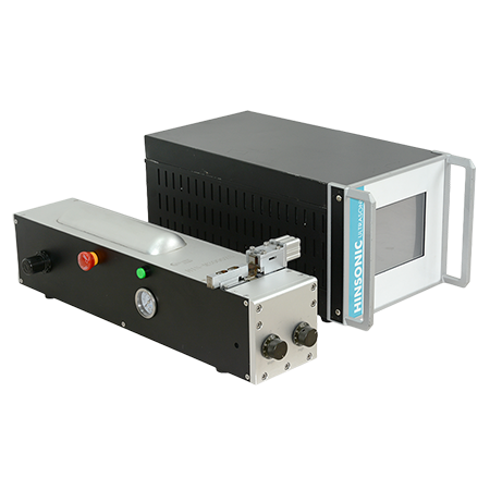
🔍 Request Your Free Sample Splicing & Metallurgical Validation Report Planning to transition your assembly line to meet SAE/USCAR-45 or USCAR-38 automotive specifications? Don’t leave your process window to chance. Send your copper or aluminum stranded wire samples to Hyusonic’s Advanced Joining Laboratory. Our metallurgists will provide you with:
ASTM E3 Metallographic Cross-Section (Microsection) Analysis.
Calibrated Tensile Shear & Peel-off Destructive Pull Tests.
Keysight 34420A 4-Wire Kelvin Micro-ohm Resistance Mapping.
Tell Us Your Need,Get A Quick Quote/Download Catalog.
Get professional technical support , we are always here.
Address
No. 168 Weita Road, Zhangpu Town , Kunshan , Suzhou , Jiangsu , China
Email Us
rui.zhang@hyusonic.com
Call Us
+86 13776317970